Planarising boom for legged robots

In the UCT Robotics Lab we have a number of legged robots which run around in the experimental area. To help them balance and provide state information for control I built a custom 2.5m carbon fibre planar support boom. The design and software for the boom is documented in a section of my thesis.
The boom uses two tensioned steel cables in a parallelogram arrangement to always keep the end vertical. A Kalman filter fuses state data from the IMU on the end and the high-resolution encoders at the base to estimate the robot position, velocity, and acceleration.
All of the parts I designed were machined in-house at UCT’s workshop. Tight tollerances were particularly important as any slop in the joints would introduce errors into the state estimates. The parts were machined from 6061 aluminium and 304 stainless steel.

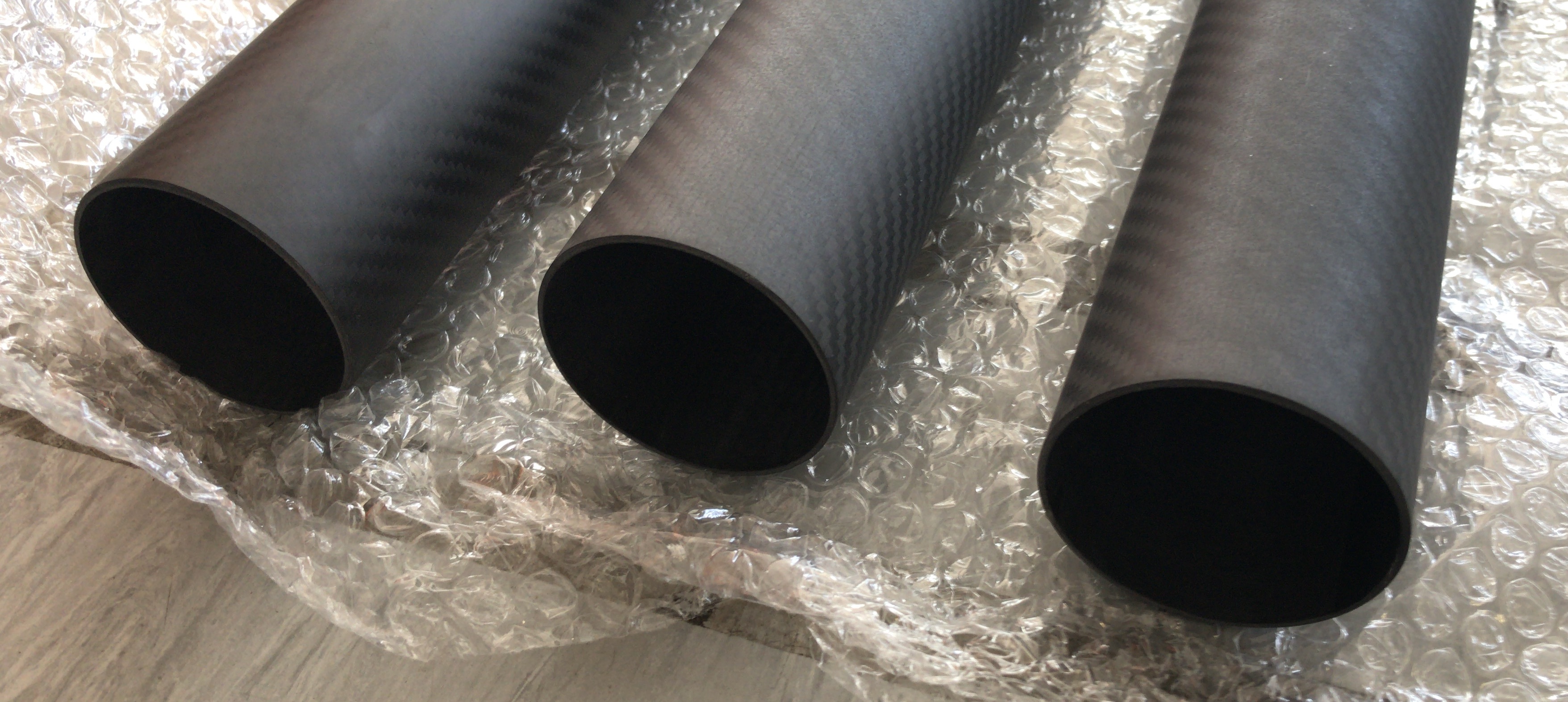
To maximise both torsional and lateral rigidity, while remaining as light as possible, the boom arm is a large diameter thin walled tube, maximising the polar moment of inertia. The arm is 2.5m long and is constructed from 3 pieces of 60mm outer diameter carbon fibre tube with a wall thickness of 1.5 mm.
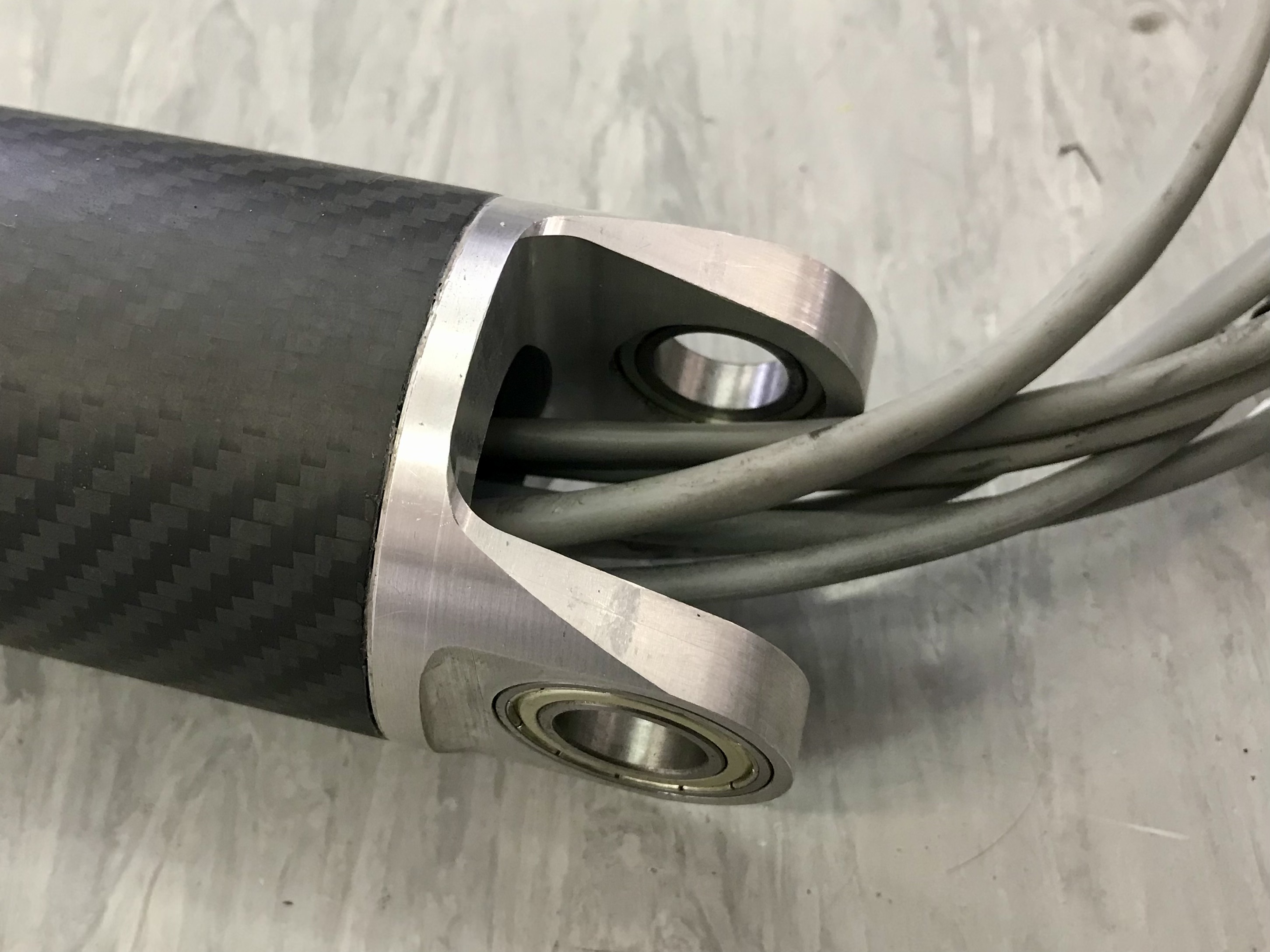
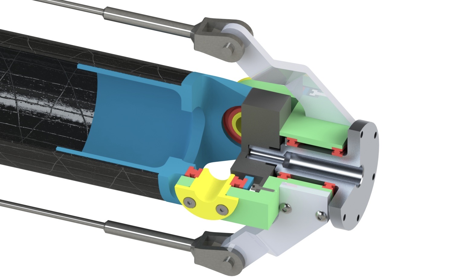
The boom was designed with interchangable mounting ends as some of the robots require the ability to pivot about the end while other needs to be rigidly attached. An incremental optical encoder is incorporated into the pivot enabled end to measure the movement of this additional degree of freedom. An accelerometer is mounted to both mounting ends.
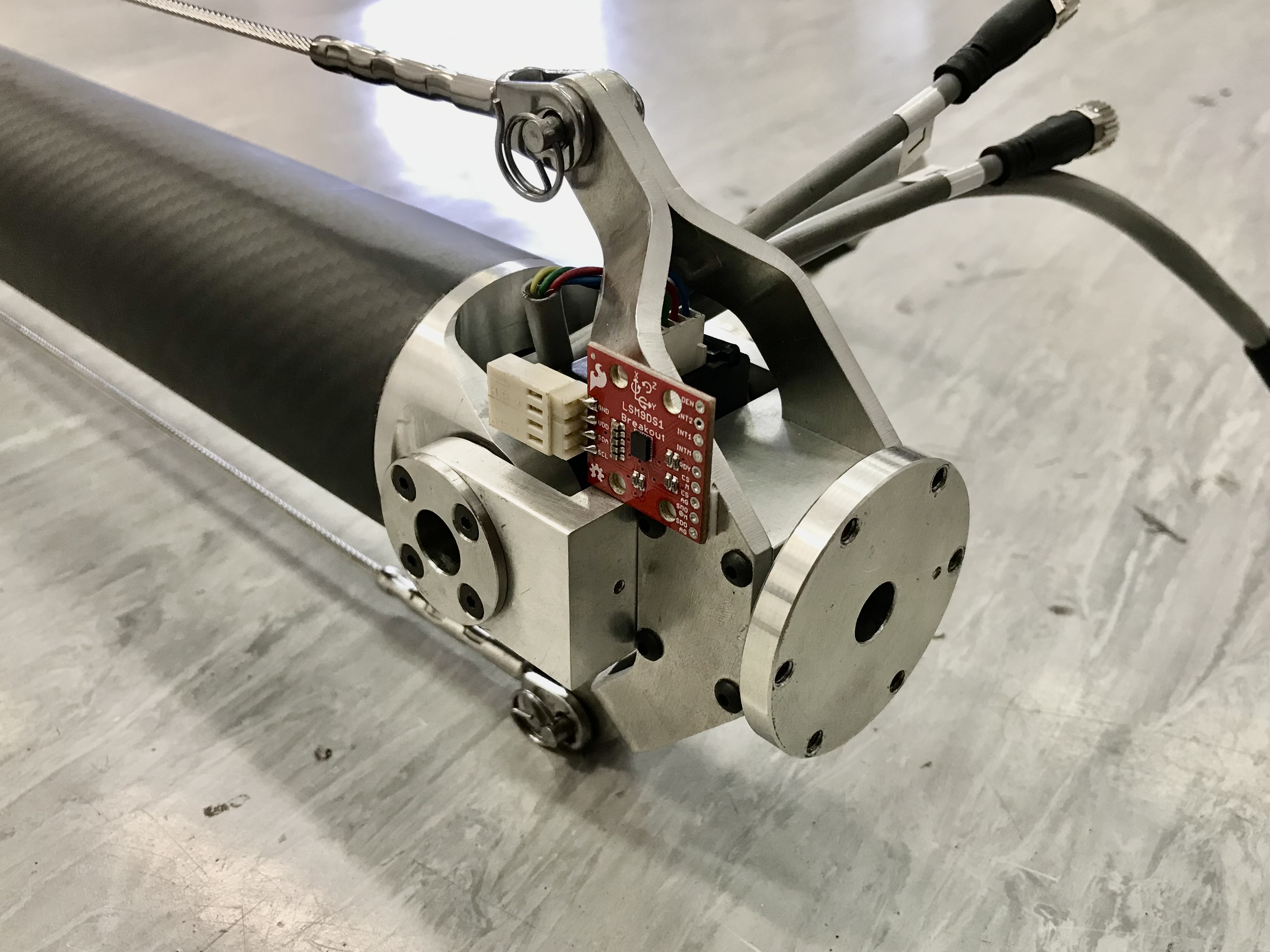
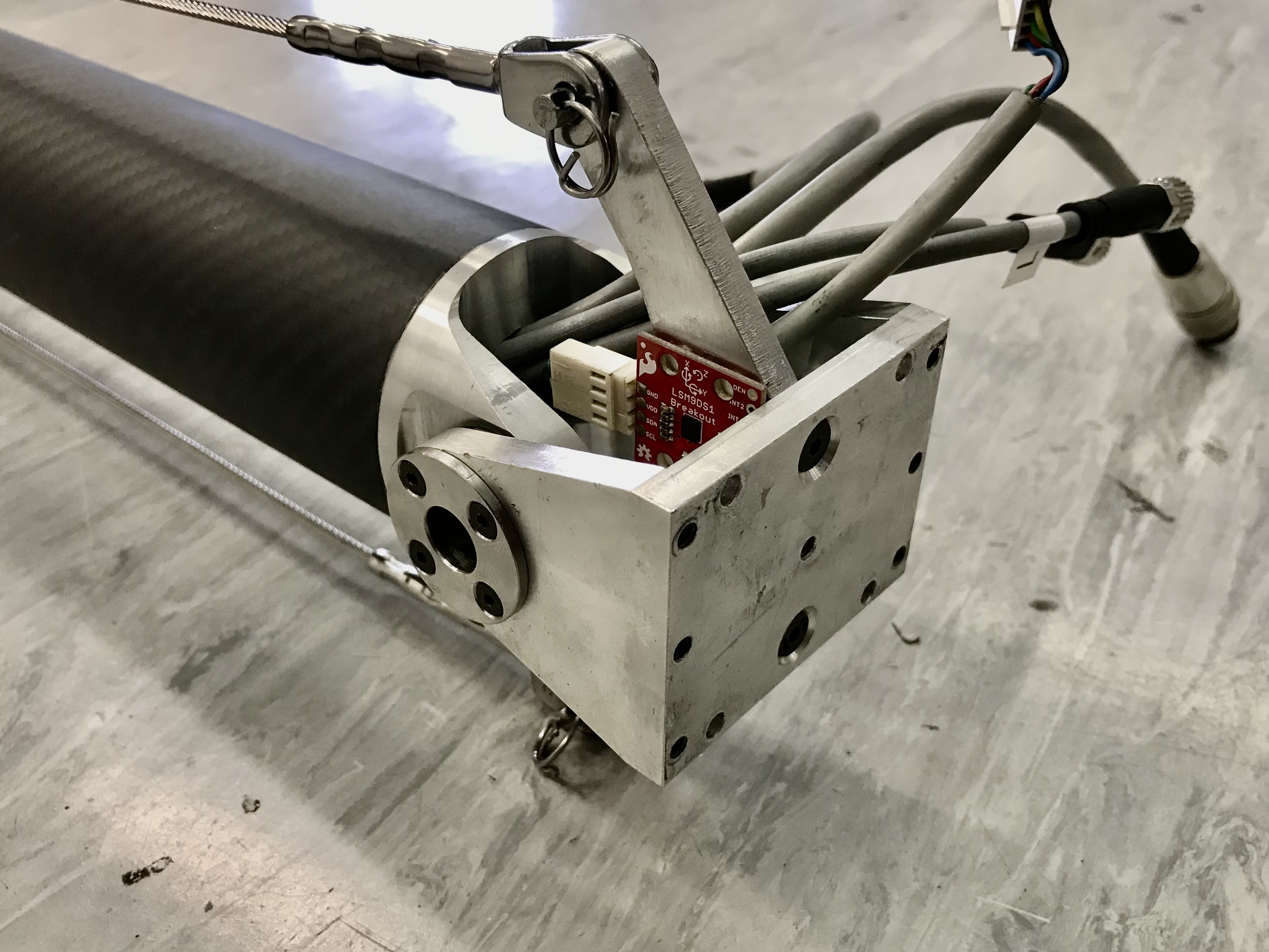
The hollow stainless steel shafts for the elevation axis on the end insert from either side to preload the bearings in a back-to-back configuration and remove any axial slop in the joint.
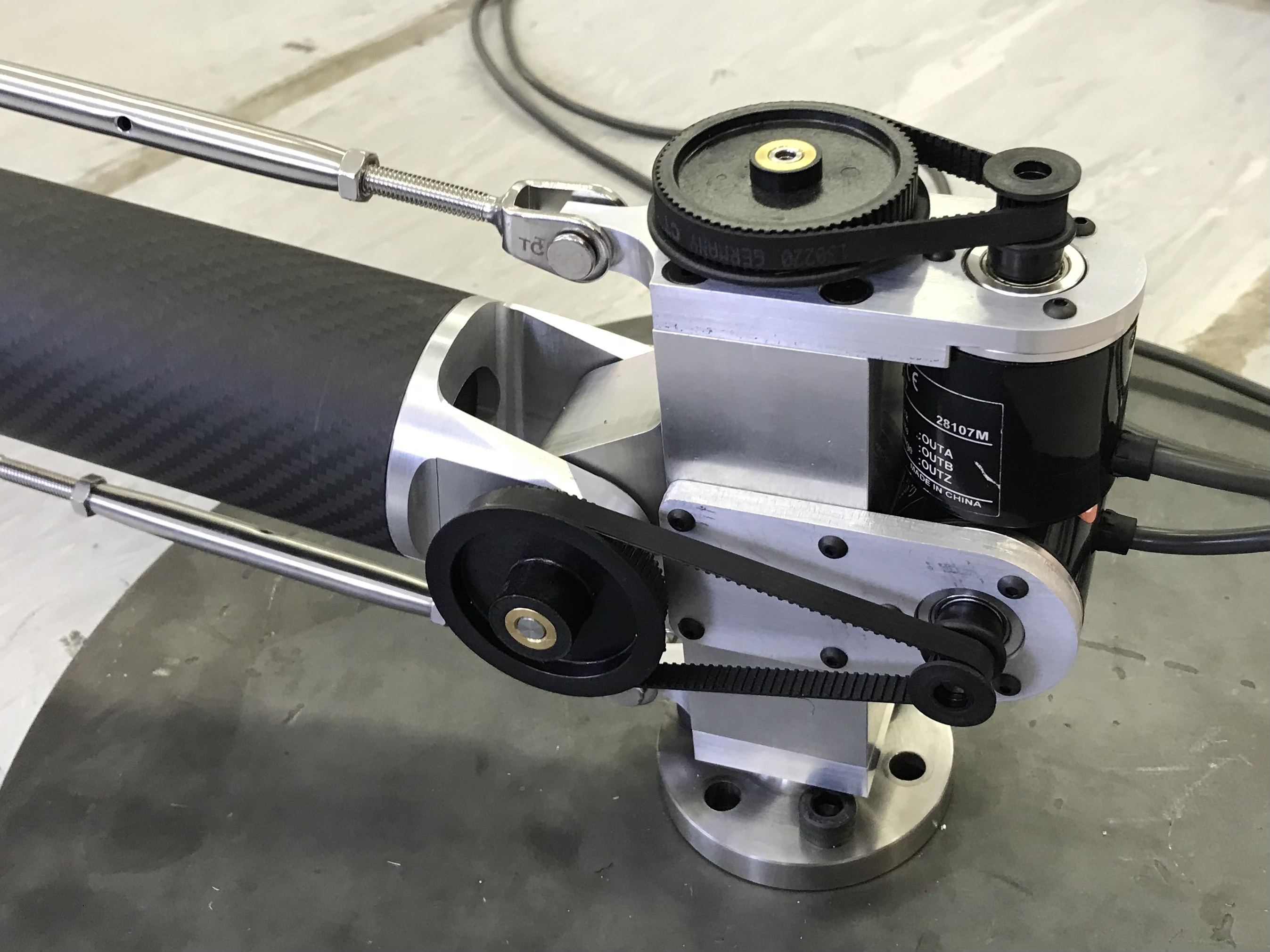
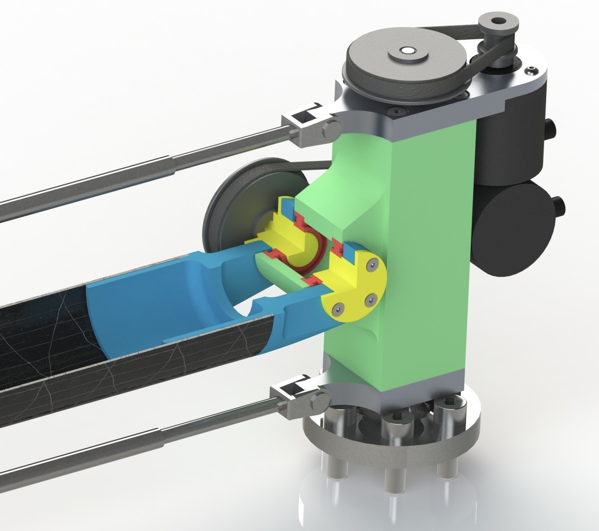
The centre pivot of the boom serves a stable base which the robot will run around, as well as the primary two degrees of freedom. An incremental quadrature encoder is mounted to each of the axes, geared with a 6mm wide MXL profile timing belt for a 4:1 gear ratio to further increase angular resolution.
Here you can see the boom doing its thing while Kemba bounds around the lab.
Enjoy Reading This Article?
Here are some more articles you might like to read next: